Grounding & Cadwelding
A tower is a lightning rod with radios on it. Exothermic ground rings, bonded surge suppression, and measured earth resistance to protect the gear, the cabinet, and the people at the site. New-build grounding to Motorola R56 and IEEE 80, post-strike remediation, and bringing old sites back to code. Cadwelded, tested, documented.
What's included.
Full tower grounding scope from a bare pad to a tested, documented earth system. New builds, retrofits, damage remediation, and bonding of everything you add after.
- Ground ring install: bare tinned copper conductor (typically 2 AWG or 2/0 AWG) trenched around the tower and equipment pad
- Ground rod install: copper-bonded steel or solid copper rods, driven to depth with hydraulic drivers
- Cadweld / exothermic bonds on every ground-ring splice, rod connection, and tower-leg bond
- Irreversible compression connectors where an exothermic weld isn’t practical
- Tower-leg bonding: every leg or monopole base bonded to the ring with redundant paths
- UFER (concrete-encased electrode) bonding where the foundation schedule allows
- Ice-bridge and cable-tray bonding along the full feedline path
- Equipment cabinet and shelter bonding, including master ground bar install and landing straps
- Surge suppression install at cabinet entry and tower-top for every Cat6, DC, and fiber-armor run
- Lightning down-conductor install on structures that call for a dedicated lightning path
- Tower-top ground kit install on fiber armor and Cat6 runs per manufacturer spec
- Generator, fuel tank, and fence-and-gate bonding to the site ring
- Soil resistivity testing (Wenner 4-point method) for site design and compliance
- Fall-of-potential ground resistance testing post-install and on inspection schedules
- Clamp-on continuity testing on every bond along the path
- Legacy-site remediation: broken bonds, corroded mechanical connectors, missing ground kits
- Post-lightning-strike assessment: melted conductors, failed surge gear, bond continuity verification
- Documentation: ground-system drawing, bond map, resistance report, and as-built package
Need grounding & cadwelding on a real deadline?
Send your site details. We come back with a quote, a crew, and a schedule.
Exothermic welds hold. Mechanical connectors drift.
The number one reason old tower sites fail a ground-system inspection is that the original crew used mechanical connectors (split-bolt, acorn, or lay-in lug) on the ring and bond points. Mechanical connectors work on day one. They don’t work on year fifteen. The bond point corrodes at the dissimilar-metal interface, the clamp torque relaxes through temperature cycles, and the resistance across the connection creeps from milliohms to ohms to kilo-ohms. By the time you notice, the surge path is gone and the next strike takes out your radios.
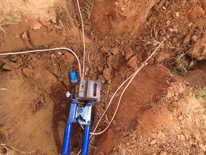
Exothermic welds (the trade name “Cadweld” covers the common mold-and-powder system) bond two conductors into a single molecular unit. A graphite mold holds the cables in place. A reducing agent (copper oxide and aluminum powder) ignites at about 1,300 °C. The reaction melts the target metals together and casts a bond that has higher ampacity than the cables going into it. There is no clamp to loosen, no interface to corrode, no torque to verify. It holds for the life of the site.
That’s the standard. Every splice on the ring, every rod connection, every tower-leg bond. Mechanical connectors are an exception we use only where an exothermic weld isn’t practical (typically on removable equipment or on painted structures where the heat would damage the coating), and then we use irreversible compression connectors rated for IEEE 837, not a lay-in lug.
Why IEEE 837 matters.
IEEE 837 is the industry standard for qualification of permanent connections used in grounding. It sets the bar a connection has to meet: current-carrying capacity under fault, mechanical strength, corrosion resistance, and long-term stability. Exothermic welds meet 837 by default. A small number of compression connectors meet 837 when installed with the manufacturer’s specified die and crimp tool. Almost no split-bolt or clamp-style connector does.
When an insurance auditor, an EOR, or a utility inspector asks how your site connections are qualified, the answer “IEEE 837” is the one that closes the review. That’s how we build.
Cadweld on steel, too.
The tower-leg bond is the most critical connection on the ring. The leg is galvanized structural steel. The ring is tinned copper. A mechanical connector at that interface will corrode galvanically, and the tower will slowly lose its bond to earth over the first five years of service.
Exothermic welds designed for copper-to-steel (a different mold and a different alloy powder than the copper-to-copper weld) solve that. The bond is cast directly onto the tower leg, sealed, and inspected. We use the steel-specific weld on every tower-leg and monopole-base bond. It’s slower and more expensive than a lug-and-bolt at install time. It’s the reason the bond is still intact in year twenty.
A grounded tower is a system, not a ground rod.
Driving a ground rod is not grounding a tower. A single 8-foot ground rod in average soil gives you maybe 25 ohms of resistance to earth. That’s not low enough for a tower, not low enough for carrier-grade radio equipment, and not low enough to survive a direct lightning strike without collateral damage.
A proper tower ground is a ring plus rods plus bonding plus surge suppression, all working as one low-impedance path to earth. Every piece matters. Leave one out, or hand-wave through one of them, and the whole thing performs worse than it should.
Here’s what a code-built ground system actually includes.
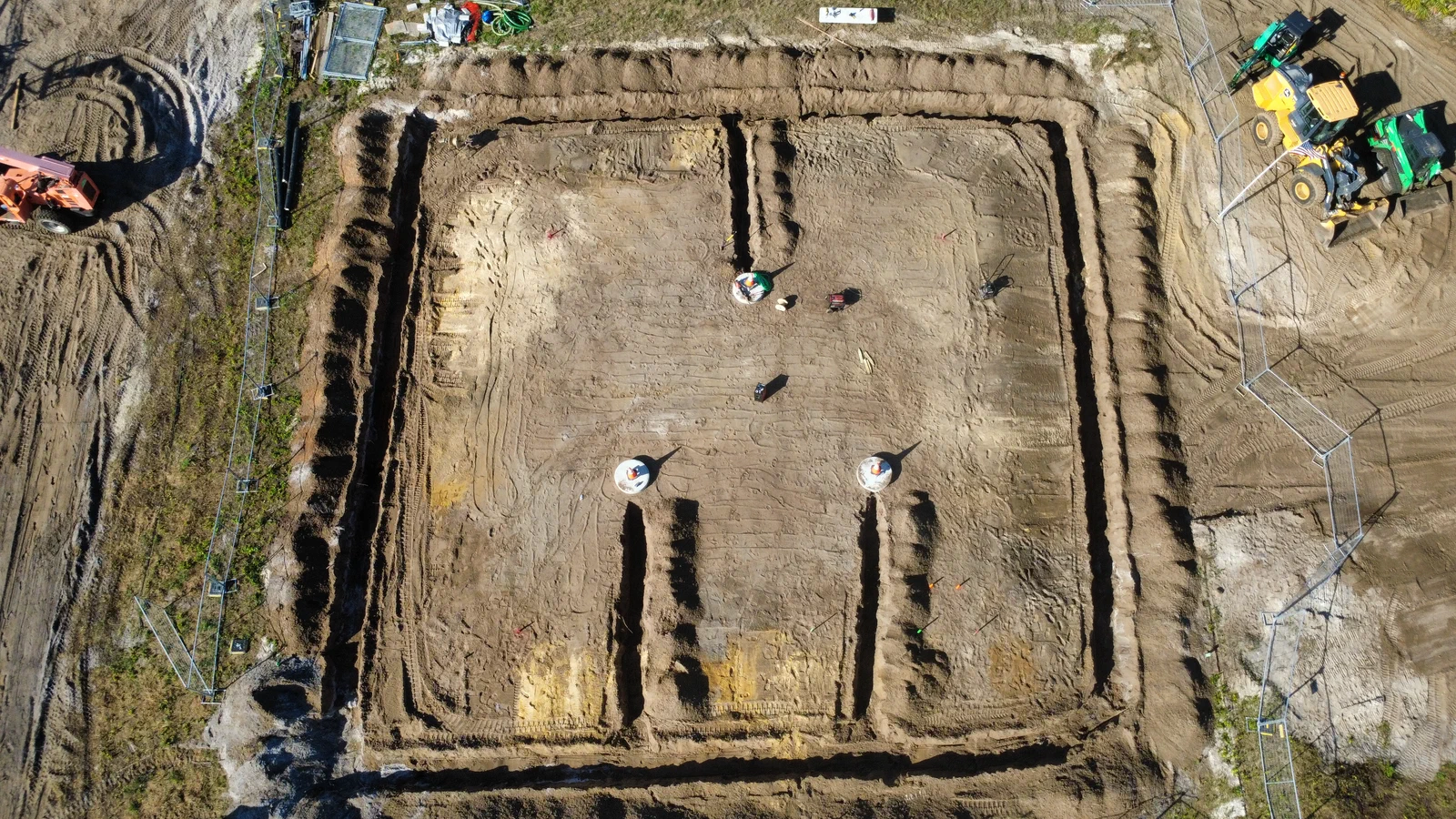
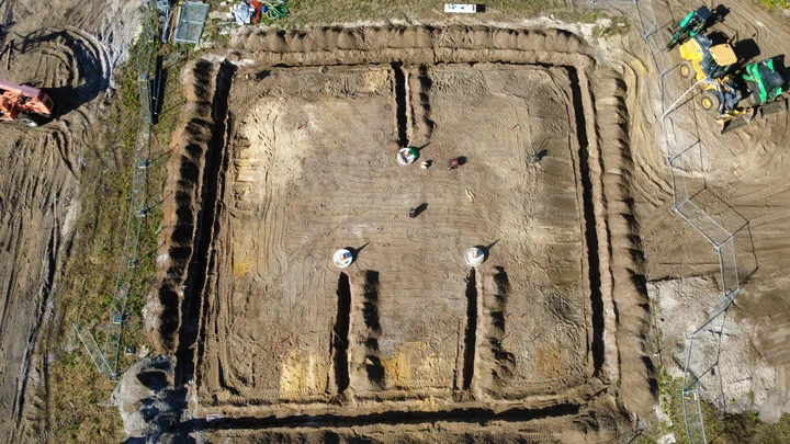
The ring and the rods.
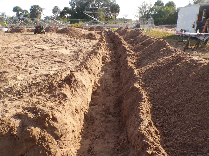
Bare tinned copper conductor (typically 2 AWG for WISP-scale sites, 2/0 AWG for carrier, utility, and public-safety) trenched 30 inches deep in a ring around the tower base and the equipment pad. The ring closes the loop so current from a strike has multiple symmetric paths to earth, not one dominant path that burns.
Ground rods driven at intervals around the ring (typically every 16 feet, minimum two per tower leg and a cluster at the cabinet). Copper-bonded steel rods are the standard; solid copper on higher-spec utility and public-safety sites. Length driven by soil conditions and target resistance, often 8 to 20 feet with couplers where a deeper single rod is called for.
Every rod bonded to the ring with an exothermic weld. Every splice in the ring itself (corner joints, connections to the cabinet ring, tap points for tower legs) is also a weld.
Tower, cabinet, and ancillary bonds.
Each tower leg or monopole base bonded directly to the ring, typically with an exothermic weld to the structural steel and a redundant path to a second point on the ring. The redundancy matters because a strike will blow out a single bond 1 in 50 times; two bonds in parallel drop that to near zero.
The equipment cabinet bonded to the ring through a master ground bar and a dedicated landing strap (not through the cabinet frame alone). Surge suppressors installed on every Cat6, DC, and fiber-armor run at cabinet entry and tower-top, bonded to the cabinet ground bar and the tower ring with short, direct runs (current wants the straight path).
Ice bridge and cable tray bonded along its run so induced current from a nearby strike doesn’t find a path through the feedlines. Fence, gate, generator, and fuel tank bonded to the ring per NEC and R56. Anything metallic on the site is either bonded in or isolated from the system; nothing is left to find its own path.
UFER where the foundation allows.
A UFER (concrete-encased electrode, named for Herbert Ufer who developed the approach during WWII) is a length of bare conductor cast into the tower or pad foundation before the concrete pour. The concrete itself is a good conductor when buried, and the hydration holds moisture over the long term. A UFER gives you a stable, low-resistance ground that’s independent of seasonal soil moisture.
On new builds where we’re coordinating with the civil crew (our own, typically), we drop a UFER into every foundation pour. It’s cheap at pour time and nearly impossible to add later. On retrofit work it’s a missed opportunity, but the ring-and-rods system does the same job with more rods.
Foundations and civil scope includes UFER install on every pour by default. If your EOR’s stamped drawing specs it, we install it.
Test it. Document it. Don't guess.
Installing a ground system without testing it is like tensioning a guy cable by feel. You think it’s right. You won’t know until the weather turns or the inspector shows up.
Every install we do ends with a measured ground-resistance test, a continuity check on every bond, and a delivered report with the numbers. That’s the deliverable, not the wire in the ground.
Fall-of-potential ground resistance.
The fall-of-potential test (IEEE 81 method) measures the actual resistance from your ground system to true earth. You drive a current probe far out from the site (typically 3x the diagonal of the ground system), a potential probe at 62% of that distance, inject a known current, and measure the voltage. The ratio is your ground resistance in ohms.
Target depends on the site class:
- WISP and light commercial: under 25 ohms per NEC is the code floor, but we target under 10 ohms on every install for surge performance.
- Carrier-grade and public-safety: under 5 ohms per R56 and most operator specs.
- Utility substation and critical infrastructure: under 1 ohm per IEEE 80 on the ground grid, with step-and-touch calculations.
The measured value goes in the commissioning report. If the target isn’t hit, we keep driving rods, extending the ring, or re-designing until the number is right. We don’t sign off on a site at “close enough.”
Soil resistivity drives the design.
Before a new-build ring goes in the ground, we measure soil resistivity using the Wenner 4-point method. Four probes at a known spacing, injected current, measured voltage, calculated resistivity in ohm-meters. The measurement is repeated at multiple depths (probe spacings) to characterize the soil profile.
Resistivity numbers drive the design:
- Low-resistivity soil (wet clay, loam): a ring and a small number of short rods will hit target.
- High-resistivity soil (dry sand, rocky fill, desert hardpan): more rods, longer rods, a larger ring, and sometimes ground-enhancement material around the rods and conductors.
On the 690 ft tower in Dothan the soil went to bedrock at 4 feet. We used deep-drilled augered rods with ground-enhancement backfill to hit the R56 resistance target. On a Florida swamp build the soil did most of the work. The ground system is designed to the site, not built from a template.
Continuity on every bond.
Resistance-to-earth is the headline number. Continuity across every bond is the other half. A clamp-on ground resistance meter on each weld, each rod-to-ring connection, and each tower-leg bond tells us whether that bond is actually making contact or whether we have a failed weld we need to re-do.
Failed exothermic welds are rare (under 1 in 100 in our field experience) but they do happen, usually when the mold wasn’t clean or the conductor ends weren’t prepped. Catching the failure during the continuity sweep lets us re-weld before backfill. Catching it in year three, after a strike fried the radios, is how insurance claims get written.
How it goes.
A new-build ground ring runs 1 to 3 days on a standard tower site. Legacy remediation and post-lightning work scales to the damage.
Design review
We pull the stamped site drawing, the R56 target class, the operator spec if there is one, and any utility or public-safety grounding requirements on top. Ground-system drawing produced (ring routing, rod count and depth, bond locations, surge-gear plan) and reviewed with the EOR if the site calls for one.
Soil resistivity survey
On new builds, Wenner 4-point survey before the ring goes in. Resistivity numbers drive final rod count and depth. On retrofits where the ring is already partly in the ground, we skip the survey and measure as-is.
Ring and rod install
Ring trench cut to 30 inches, bare tinned copper conductor laid in. Ground rods driven with a hydraulic driver, extended with couplers where depth calls for it. UFER conductor cast into the foundation pour on new work.
Exothermic bonding
Every rod-to-ring splice, every ring corner, every tower-leg bond, and every tap point welded with the right cadweld mold and powder for the conductor materials. Weld caps inspected and photographed. Mechanical-connector exceptions (only where a weld isn’t practical) done with IEEE 837-qualified compression connectors.
Cabinet, ice bridge, and surge
Master ground bar landed at the cabinet with a dedicated strap to the ring. Ice bridge and tray bonded. Surge suppressors installed at cabinet entry and tower-top for every Cat6, fiber-armor, and DC run, bonded short and direct.
Testing and verification
Fall-of-potential ground resistance test to earth, measured against the target for the site class. Clamp-on continuity test on every bond. Anything outside spec is re-worked before backfill closes the ring.
Documentation
Ground-system drawing, bond map, resistance report (pre- and post-install where retrofits were involved), continuity log, and photo record of every weld before backfill. Your EOR, your operator, and your insurance auditor have everything they need.
Built to standard. Measured to code.
Every ground system we install is held to the spec the site calls for, not a generic template. Commercial WISP sites build to R56. Utility and public-safety sites build stricter.
Motorola R56
Standards and Guidelines for Communication Sites. The industry-default spec for commercial, WISP, carrier, and public-safety tower grounding. Covers ring design, rod placement, exothermic bonding, surge suppression, and resistance targets. R56 is our default on every install unless the site calls for stricter.
IEEE 80
Guide for Safety in AC Substation Grounding. The utility-industry spec for step-and-touch voltage, ground-grid design, and fault-current performance. Applied on utility-owned towers, SCADA sites, and any project where a utility PE is driving the ground-system design.
IEEE 81
Guide for Measuring Earth Resistivity, Ground Impedance, and Earth Surface Potentials. The method reference we use for fall-of-potential testing and Wenner 4-point soil resistivity surveys.
IEEE 837
Qualifying Permanent Connections Used in Substation Grounding. The qualification spec that exothermic welds meet by default and that our compression-connector exceptions are tested against. When an auditor asks how bonds are qualified, this is the answer.
NEC Article 250
National Electrical Code general bonding and grounding. Covers equipment grounding, bonding conductor sizing, and the electrical-service side of the site ground system.
NEC Article 810
NEC provisions for radio and television equipment. Feedline grounding, antenna discharge units, and the 20-ft rule for lead-in conductors to the grounding electrode.
NFPA 780
Standard for the Installation of Lightning Protection Systems. Covers dedicated lightning down-conductors, air terminals, and the bonding-and-protection scheme for structures with a lightning protection system on top of the tower ground.
UL 96 / UL 96A
Listing specifications for lightning protection components (rods, conductors, connectors) and master-labeled lightning protection system design. We install UL-listed components on sites that carry the certification.
TIA-222-I
ANSI structural standard for antenna-supporting structures. References the grounding and bonding requirements we build against on every tower we touch, including ground-ring conductor sizing and bond locations.
Gear & certifications.
Equipment
- Cadweld / exothermic welding kits with mold library for copper-to-copper, copper-to-steel, and cable-to-rod bonds
- IEEE 837-qualified compression connectors and calibrated dies for non-weld exceptions
- Hydraulic ground-rod drivers and extension couplers for rods to 40+ ft
- Clamp-on ground resistance testers for continuity verification on every bond
- Fall-of-potential test sets for earth-resistance measurement per IEEE 81
- Soil resistivity meters for Wenner 4-point surveys on new-build sites
- Trencher, rock saw, and directional-boring rigs for ring install through tough soil
- Master ground bar, ground kit, and surge-suppression inventory (Polyphaser, Huber+Suhner, Transtector)
- Ground-enhancement material (GEM, bentonite, conductive cement) for high-resistivity sites
- Self-contained crew trailers: welding kit, rod inventory, cable spools, and test gear
Certifications & insurance
- NATE ClimberSafe and SafetyLMS-certified climbers on every crew
- ANSI A10.48 qualified tower hands
- Motorola R56 and IEEE 80 trained lead installers
- Exothermic welding manufacturer training (Cadweld, nVent Erico)
- OSHA 10 / 30 compliant
- Fully insured: general liability and workers’ compensation
Questions we get a lot.
What is cadwelding and why does it matter?
Cadwelding is the common trade name for exothermic welding. A graphite mold holds two conductors in position, a powdered copper-oxide-and-aluminum reducing agent is ignited at about 1,300 °C, and the reaction melts and casts the conductors into a single molecular bond.
It matters because a cadweld:
- Has higher current-carrying capacity than the cables going into it.
- Has no clamp, no torque, and no bolt to loosen over time.
- Has no dissimilar-metal interface to corrode.
- Meets IEEE 837 (qualification of permanent connections used in grounding) by default.
Mechanical connectors (split-bolt, acorn, lay-in lug) fail slowly over a decade of temperature cycling and corrosion. Cadwelds don’t. That’s why every bond point on a correctly-built ground system is a weld, not a clamp.
What ground resistance do I need?
Depends on the site. Rough targets:
- NEC code floor: under 25 ohms for a single electrode. That’s a starting point, not a real target.
- WISP and light commercial: under 10 ohms is what we aim for in practice.
- Carrier-grade and public-safety: under 5 ohms per Motorola R56 and most operator specs.
- Utility substation, SCADA, and critical infrastructure: under 1 ohm per IEEE 80 on the ground grid, with step-and-touch voltage calculations.
The measured value at handover is documented in the commissioning report. If the target isn’t hit on the first pass, we keep driving rods, extending the ring, or adding ground-enhancement material until it is.
What is Motorola R56?
R56 is the colloquial name for Standards and Guidelines for Communication Sites, a grounding, bonding, and surge-protection spec published by Motorola Solutions. It is the industry default on commercial tower, WISP, carrier, and public-safety sites across the U.S.
R56 covers ring design, ground-rod placement and spacing, exothermic bonding, cabinet grounding, surge suppression, ice-bridge bonding, down-tower cable grounding, and resistance targets. When an RFP or operator spec says “to R56,” this is what they mean. We build to R56 by default on every site.
When do I need IEEE 80 instead of R56?
Do you test the ground system after install?
Yes, every site. Two measurements every visit:
- Fall-of-potential test (IEEE 81 method) for earth-resistance measurement to true earth.
- Clamp-on continuity on every exothermic bond, every rod-to-ring connection, and every tower-leg bond.
Results go in the delivered commissioning report. If the resistance target isn’t hit, we re-work the system. If any bond shows a continuity failure, we re-weld before backfill.
Can you retrofit or upgrade an older site?
Yes, most of our remediation work is exactly this. Common scenarios:
- Old site with split-bolt or acorn connectors on the ring, drifted out of tolerance.
- Tower-leg bonds corroded through at the galvanized-to-copper interface.
- Missing surge suppression on one or more feedlines.
- No ground kits on the down-tower fiber armor or Cat6.
- Ice bridge or cable tray never bonded.
- Ground ring never closed into a full loop.
We audit what’s there, measure the current ground resistance, identify the gaps, quote the fix, and bring the site back into R56 compliance. Maintenance and inspection scope includes ground-system audit as a line item on every visit.
What about after a lightning strike?
Post-strike assessment is a specific scope. A direct or near-direct lightning strike will commonly:
- Vaporize undersized ground conductors at the tower top and mid-points.
- Weld or burn through surge-suppression gear (the gear is doing its job when it does that; it needs replacement).
- Blow the bonds off feedline ground kits along the down-tower run.
- Damage antennas, radios, and (in bad cases) cabinet electronics despite the surge path.
We do a full post-strike walk: visible damage on conductors and gear, continuity test on every bond, resistance-to-earth re-measurement, surge gear replacement, and coordination with your insurance adjuster on the damage scope. Crews typically mobilize within 24 to 48 hours of a strike call in the lower 48.
Do you use solid copper or copper-bonded rods?
Depends on the spec and the site.
- Copper-bonded steel rods are the standard default and are approved under R56. A thick copper jacket over a steel core. Fine for most WISP, commercial, and carrier work. Lower cost, easier to drive in tough soil.
- Solid copper rods are called for on utility substations, high-corrosion coastal sites, and on most IEEE 80 jobs. Higher cost, longer service life, better corrosion performance.
Your EOR or operator spec drives the call. If you don’t have one, we default to copper-bonded and explain the tradeoff.
Do you bond the fence, gate, generator, and fuel tank?
Yes, everything metallic on the site is either bonded to the ring or deliberately isolated. Specifically:
- Fence fabric and posts bonded per NEC 250.194 where the fence is within the influence zone of the tower.
- Gate bonded through a flexible bonding jumper across the hinge so the gate ground isn’t dependent on the hinge pin.
- Generator frame bonded to the ring, with transfer-switch ground bonded per NEC Article 250 (separately-derived system rules).
- Fuel tank bonded per NFPA 780 and per your fuel provider’s requirements (some require a separate dedicated electrode).
- Propane bottles and aboveground piping bonded to the ring.
Nothing metallic finds its own path to earth. That’s how step-and-touch voltages get people killed during a strike event.
Do you handle surge suppression too?
Yes, it’s part of every ground scope. We spec, install, and bond surge-suppression gear on every Cat6, DC, and fiber-armor run at cabinet entry and tower-top. Brands we install daily:
- Polyphaser (the default on most RF work).
- Huber+Suhner on carrier-grade and microwave paths.
- Transtector and ITW Linx on DC power and Ethernet runs.
Bonding runs from the suppressor to the cabinet ground bar and the tower ring are short, direct, and 2 AWG or heavier. Current wants the straight path; we give it to it.
Do you do UFER (concrete-encased) grounding?
Do you handle lightning protection systems (air terminals and down-conductors)?
How long does a new ground ring install take?
- Standard WISP / commercial site (single tower, single cabinet): 1 to 2 days.
- Carrier-grade or CBRS site with fiber plant: 2 to 3 days.
- Utility-grade IEEE 80 site with step-and-touch analysis: 3 to 5 days, including the resistivity survey and formal grid design.
- Post-lightning remediation on an existing site: 1 to 3 days depending on the damage scope.
Soil conditions drive a lot of the variation. Trenching through sand is a day. Trenching through rocky fill with a rock saw is three.
How much does this cost?
Fixed fee on defined scope, with unit rates and change orders for field conditions. Quoted against tower type, soil, ring length, rod count, and surge-gear scope. Rough ranges:
- Standard WISP / commercial ground ring, new build: mid four to low five figures.
- Carrier-grade site with full surge plant: mid five figures.
- Utility-grade IEEE 80 install with resistivity survey and formal grid: upper five to low six figures.
- Legacy-site remediation: quoted against the audit, typically mid four to mid five figures.
- Post-lightning assessment and repair: quoted against damage scope.
Send us the site and you’ll have a line-itemed quote inside a week.
Do you do grounding work on towers you didn't build?
What's your service area?
How do I get started?
Send us the site (address or coordinates), the tower type, and the scope (new-build, retrofit, post-strike, or compliance audit). If you have a stamped drawing or a prior ground-system report, include it.
Request a quote here or call us at (763) 280-6050. Scheduled work typically quoted inside a week. Post-strike work quoted the same day.
Don’t see your question? Ask us directly. We answer every scoping call.
Related services.
Foundations & Civil
Excavation, rebar, concrete, grading, fencing, and ground rings.
New Site Builds
Empty dirt to operational tower, one crew, one point of contact.
Tower Erection
Guyed, self-supporting, and monopole structures up to 300ft.
Antenna & Radio Install
Antennas, radios, fiber, DC, and Cat6. Ubiquiti, Cambium, Mimosa, Tarana, Nokia, and more.
Maintenance & Inspection
Inspections, repairs, and post-storm response for a 20-year asset.
Page last updated July 13, 2026.
Tell us the site.
We'll bring the steel.
Send the location, tower type, scope, and timeline. We come back with a quote, a crew, and a schedule you can build a business around.