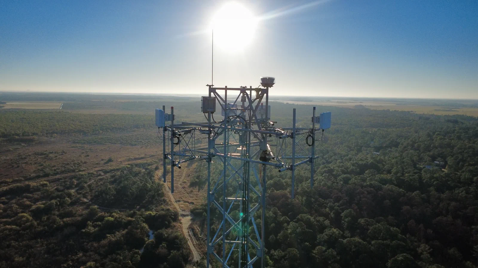
Sector Antennas & Backhaul Installation for WISP, CBRS LTE, and Public-Safety
The RF work that turns a tower into a revenue-generating asset. Sector antennas, PTP backhaul, CBRS LTE, and horn arrays, mounted and aligned to manufacturer spec. WISP-scale gear done right, not macro-cell overkill priced in. Primary construction partner for The Edge Mile on Nokia and Baicells CBRS buildouts.
What's included.
Full RF install scope from a pallet of gear on the ground to aligned, commissioned, and documented coverage in the air. Fiber plant, DC, Cat6, and alignment under one scope of work.
- Sector antenna mounting at 65°, 90°, and 120° patterns, 1 to 8 ft height depending on gain and pattern
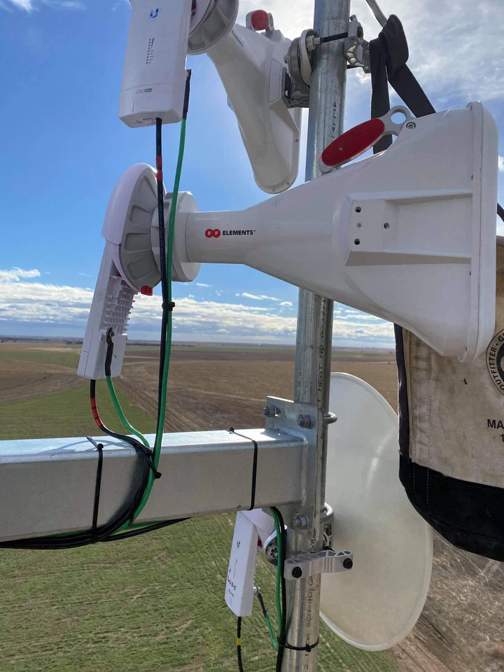
- Horn antenna arrays (RF Elements: Symmetrical, UltraHorn, Asymmetrical, full pattern range)
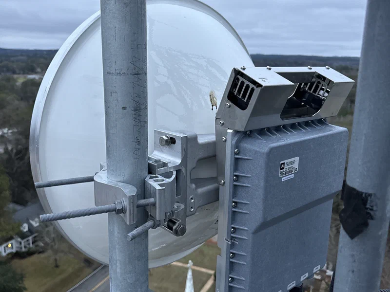
- Backhaul dish install, 1 to 6 ft diameter, from WISP-class PTP up to carrier-grade microwave
- Point-to-point link install and ring topology deployments for backhaul redundancy
- CBRS LTE eNB install (Nokia AZQC, Baicells) with SAS coordination
- Multi-carrier sector array layout (up to 4+ carriers per sector)
- Custom mount and bracket fabrication where the site demands it
- Fiber plant: single-mode fiber runs down-tower, splice enclosures, and cabinet termination
- DC power runs to each radio per vendor spec (typically 12, 24, or 48 V)
- Cat6 / Cat6A shielded Ethernet runs with PoE injectors and surge protection
- Precision alignment: azimuth, downtilt, roll, and link-aim verification
- Precision antenna alignment for tight-tolerance sector work (Nokia AZQC, single-channel reuse)
- Insertion-loss testing on fiber, link verification on every radio using the platform’s native diagnostics
- Surge and lightning suppression at every cabinet bulkhead and tower bottom
- Grounding and bonding to NEC Article 810 and Motorola R56
- Commissioning documentation: fiber insertion-loss logs, alignment logs, link-budget records, as-built drawings
Need sector antennas & backhaul installation for wisp, cbrs lte, and public-safety on a real deadline?
Send your site details. We come back with a quote, a crew, and a schedule.
WISP gear is smaller. Your install doesn't need carrier-scale overhead.
A carrier macro-cell sector can weigh 80 pounds and run 7+ feet tall on a long passive feed-line. WISP and CBRS sectors commonly run 1 to 8 feet tall depending on gain and pattern, mount their radio directly at the antenna, and run fiber, DC, and Cat6 down the tower instead of a heavy passive feed-line plant.
Smaller gear. Simpler mounts. Alignment driven by the radio’s own RSSI and SNR readout and platform-native alignment tooling, not by swinging 80 pounds of passive antenna on a gin-pole.
We built the company around this work. Our RF crews run WISP and CBRS-scale gear every week, with crew sizes, schedules, and hourly rates priced against that scale. We don’t dispatch a five-person carrier climb crew to hang an airFiber dish.
Platforms we install every week.
- Ubiquiti: airFiber 5XHD (PTP), airFiber 4X (4.9 GHz Public Safety Band PTP), AirMAX sectors, UISP Wave, LTU access. We know the mount hardware, the alignment tools, the firmware gotchas.
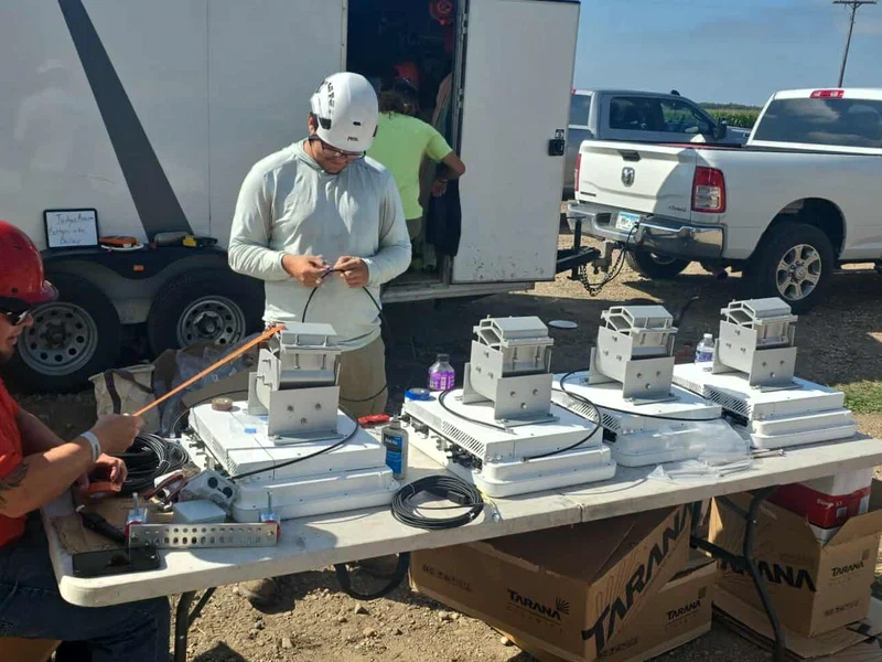
- Tarana: the full G1 platform (G1 BN, G1 RN, G1 RN Mini) and the newer G2 platform. nLOS fixed-wireless, BEAD-program friendly, common on state-grant buildouts.
- Cambium: ePMP, PMP, PTP backhaul, cnWave 60 GHz, cnMatrix switching for tower-top aggregation.
- Mimosa (Airspan): A5/A6 sector access, B5/B11 backhaul, C-series CPE.
- Nokia: carrier-grade microwave, Fastmile FWA, and Nokia AZQC CBRS site kits with 4T4R RRHs and tested antennas.
- Baicells: 436Q CBRS eNB and companion CBRS gear, often paired with The Edge Mile’s in-house EPC for full private-LTE stacks.
- RF Elements: full horn lineup (Symmetrical, UltraHorn, Asymmetrical), TwistPort shielding, StationBox enclosures, and EasyBracket mounting for interference-dense sites.
If your platform isn’t on that list, we’ll learn it. RF install fundamentals don’t change brand to brand.
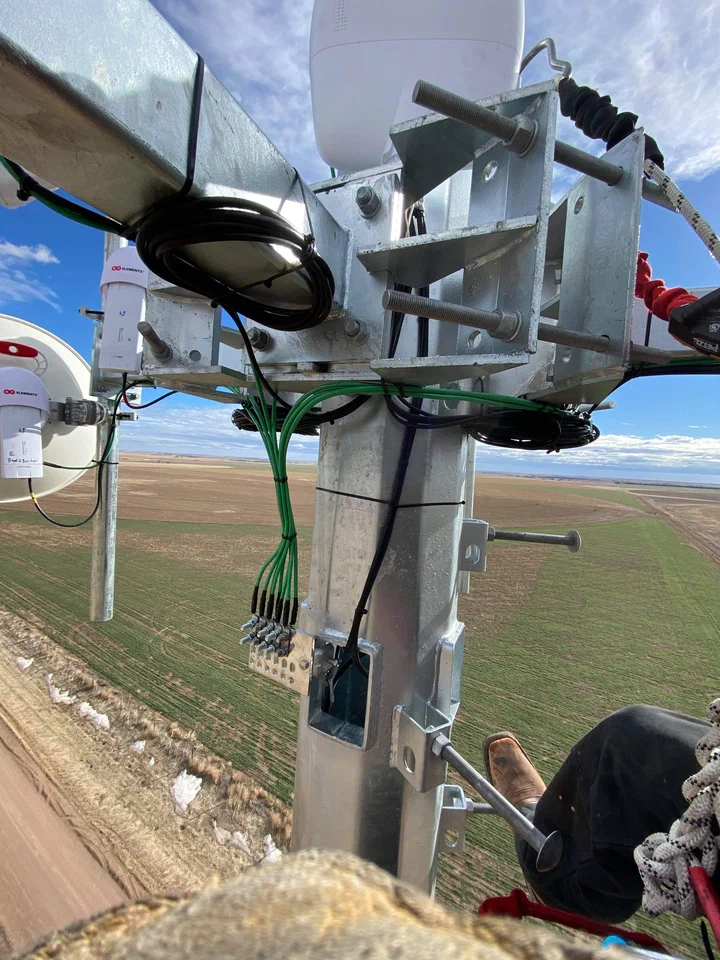
Cabling is fiber, DC, and Cat6.
WISP, CBRS, and modern public-safety deployments mount the radio at the antenna. What comes down the tower is:
- Single-mode fiber trunk. From a tower-top mux or directly from radios with fiber optics, down to a cabinet-mount splice enclosure or SFP drop. We run fiber plant end-to-end, including splicing, insertion-loss testing, and connector polish on every termination.
- DC power cable. Most tower-top radios need separate DC (12, 24, or 48 V) from a cabinet-mount power supply. Sized to run length to avoid voltage drop, with circuit protection at each end.
- Cat6 / Cat6A shielded Ethernet. For PoE-fed radios, outdoor-rated foil-shielded cable, with weather-sealed RJ-45 connectors and PoE surge protectors at the cabinet side.
Grounding, bonding, and surge protection all handled to NEC Article 810 and Motorola R56. Every cable type gets its own bonding treatment.
Alignment is a craft. Precision-aligned when the RF demands it.
A backhaul dish two degrees off is a broken link the first time the weather turns. Our standard alignment workflow on every dish and sector:
- Rough azimuth off the tower against compass bearing and stamped RF design.
- Fine azimuth and roll using the radio’s RSSI and SNR readout, both ends transmitting.
- Downtilt verified with a digital level on the antenna mount surface.
- Alignment lock with bracket torque per manufacturer spec. No cam-over kits that slip.
- Link budget verified against design, logged in the commissioning doc.
For tight-tolerance deployments like Nokia AZQC sector arrays running single-channel reuse, we use precision alignment to hit the azimuth precision those designs need. Single-channel reuse only works when each sector’s azimuth is dialed tight enough that adjacent sectors don’t swamp each other’s channel. A 0.25-degree precision-aligned sector holds where a compass-and-eyeball sector drifts.
Public-safety and 4.9 GHz work.
We’ve built 4.9 GHz Public Safety Band point-to-point rings for county-level public-safety networks, documented back to a January 2019 Georgia buildout (“rock-solid point-to-point ring all around the county”). Public-safety RF comes with specific licensing, coordination, and operational constraints:
- FCC Part 90 licensing verified before install, no first-time operation until coordination is complete.
- Interference-avoidance alignment against other licensed users in the area.
- Hardening to match county emergency-ops uptime expectations: battery backup, generator tie-in coordination, redundant paths where the budget supports it.
- Documentation that passes an auditor from the state broadband office or a FirstNet regional coordinator.
County IT directors, sheriff’s comms officers, and emergency-management coordinators scoping a 4.9 GHz buildout, call us.
LTE deployment partner: The Edge Mile.
Vertical Axis is the primary construction partner for The Edge Mile, a private LTE consultancy specializing in Nokia and Baicells CBRS deployment with an in-house EPC. The two teams work hand-in-hand on LTE buildouts. Edge Mile handles the radio-access layer, core network, and EPC integration. Vertical Axis handles the steel, the RF install, the cabling, and the site work.
If you’re scoping a CBRS LTE buildout and you’re talking to one of us, you’re likely going to end up talking to both. Private-LTE sites have more moving parts than a standard WISP install. A general tower contractor who’s never handled a SAS registration or a Nokia AZQC alignment is the wrong team for that scope.
How it goes.
A typical install runs 1 to 3 days on-site per tower for a standard 4-sector + 2-backhaul build. CBRS LTE deployments run longer due to SAS registration, EPC integration, and tighter alignment tolerances.
Pre-install review
Stamped RF design reviewed against the gear on the pallet. Mount hardware checked against the tower’s connection plates. For CBRS work, SAS registration status verified and EPC integration plan confirmed with The Edge Mile or your EPC team. Anything missing or mis-fabricated flagged before we climb.
Gear stage and rigging
Antennas, radios, cables, and mount hardware staged at the tower base. Rigging plan walked. Tag lines, hand lines, and hoist setup checked. Fiber drums and DC spools laid out for tower-down runs.
Mount hardware installation
Mount brackets installed on the tower per design. Torque verified per manufacturer spec. Alignment reference marks (azimuth and downtilt) set before any antenna goes on. On guyed towers, we stage installs around the guy radius so the rigging doesn’t foul.
Antenna and radio install
Each antenna mounted, oriented to rough azimuth, and bolted in. Radios mounted at the antenna or on the sector bracket. Jumpers run. Weatherproofing applied to every RF and data connector per manufacturer spec (mastic under tape, two full wraps). The weatherproofing is what determines whether the link lasts two years or twenty.
Fiber, DC, and Cat6 runs
Cable runs down the tower, bracketed at spec intervals. Fiber splices pulled into the cabinet splice enclosure. DC cable sized for run length, circuit-protected at both ends. Cat6 shielded, weatherproofed, and surge-protected at the cabinet bulkhead. Every conductor grounded to the tower ring at top, bottom, and at cabinet entry.
Alignment and commissioning
Fine alignment done with both ends of each link live, using the platform’s native diagnostics (RSL, SNR, packet error rate, modulation lock state). Precision-aligned where the design calls for it (Nokia AZQC single-channel reuse and similar tight-tolerance work). Insertion-loss verified on fiber. Link budget checked against RF design. For CBRS work, SAS grant confirmed and neighbor-cell measurement verified.
Punch-list and demob
Walk the site with your engineer. Cable tray tidied, cabinet terminations labeled, unused gear returned. Commissioning documentation delivered: fiber insertion-loss logs, alignment logs, link-budget verification, grounding inspection, as-built drawings, photo record.
Built to standard. Installed to spec.
Every antenna, radio, fiber splice, and mount install is held to manufacturer spec and the governing federal codes. Marginal installs don’t survive year-one storms.
TIA-222-I
ANSI structural standard for antenna-supporting structures. Drives equipment-loading math (wind and ice on the antenna cross-section) for every install. If your design wasn’t loaded for the gear you’re adding, we tell you before it goes on.
Manufacturer specifications
Every antenna, radio, fiber connector, and mount installed per the manufacturer’s published spec. Bend radius, torque, polish grade, weatherproofing, grounding. To spec, not close to it.
FCC Part 15 / Part 101
Part 15 rules for unlicensed (WISP access and most PTP in 5 / 24 / 60 GHz) and Part 101 for licensed fixed microwave (11, 18, 23, 80 GHz). We respect EIRP caps, coordination requirements, and licensing obligations at install time.
FCC Part 96 (CBRS)
Citizens Broadband Radio Service rules for the 3.55 to 3.7 GHz band. SAS registration, PAL and GAA tier coordination, and CPI-certified deployment handled on every CBRS build.
FCC Part 90
Rules for Public Safety and Private Land Mobile Radio, including 4.9 GHz public-safety PTP rings. License coordination verified before on-air.
Motorola R56 / IEEE 80
Grounding and bonding specs for communication sites. Default on WISP and commercial sites, stricter IEEE 80 and 837 on utility-grade installs.
NEC Article 810
National Electrical Code provisions for radio equipment, feedline grounding, lead-in conductors, and equipment bonding. Governs DC runs, Cat6 shielding, and fiber-armor bonding where applicable.
NFPA 780
Lightning protection standard. Surge suppressors at every bulkhead, bonded to the tower ring, installed before any radio goes on-air.
OSHA 1926 / ANSI A10.48
Federal and industry safety standards for work at height. 100% tie-off, authorized climber rescue, site-specific safety plan on every install.
Gear & certifications.
Equipment
- Climb team with 100% tie-off and authorized rescue capability on every crew
- Platform-native alignment tooling for Ubiquiti, Cambium, Mimosa, Tarana, Nokia, and Baicells gear
- Precision antenna alignment tooling for tight-tolerance sector work (Nokia AZQC single-channel reuse)
- Fusion splicers and OLTS (optical light-source / power-meter) sets for fiber plant install and insertion-loss testing
- Connector polish kits and inspection microscopes for fiber terminations
- Native-radio diagnostics for on-site interference checks and commissioning (Ubiquiti, Cambium, Tarana, Mimosa platform tooling)
- Digital levels and inclinometers for downtilt and roll verification
- CBRS SAS registration coordination via The Edge Mile’s in-house EPC stack
- DC power supplies, surge suppressors, and shielded Cat6A for WISP and CBRS stacks
- Weatherproofing supplies: mastic, 3M temflex, butyl rubber (manufacturer-spec only)
- Cadweld and mechanical bonding tooling for grounding
- Self-contained crew trailers: rigging, RF tooling, fiber gear, and spares travel with us
Certifications & insurance
- NATE ClimberSafe and SafetyLMS-certified climbers
- Platform-fluent installers on Ubiquiti, Cambium, Mimosa, and Tarana platforms
- CBRS Certified Professional Installer (CPI) training on lead CBRS hands
- FCC General Radiotelephone Operator License (GROL) on lead RF hands
- Fiber splicing and insertion-loss-testing certified technicians
- OSHA 10 / 30 compliant crews
- Fully insured: general liability and workers’ compensation
Questions we get a lot.
What RF platforms are you fluent in?
Our crews install the following every week:
- Ubiquiti: airFiber 5XHD and 4X (including 4.9 GHz public-safety PTP), AirMAX sectors, UISP Wave, LTU.
- Tarana: the full G1 platform (G1 BN, G1 RN, G1 RN Mini) and the newer G2 platform. nLOS fixed wireless, BEAD-common.
- Cambium: ePMP, PMP, PTP backhaul, cnWave 60 GHz, cnMatrix.
- Mimosa (Airspan): A5/A6 access, B5/B11 backhaul, C-series CPE.
- Nokia: carrier-grade microwave, Fastmile FWA, and Nokia AZQC CBRS site kits.
- Baicells: 436Q CBRS eNB and companion CBRS gear.
- RF Elements: full horn lineup (Symmetrical, UltraHorn, Asymmetrical), TwistPort shielding, StationBox enclosures, EasyBracket hardware.
If your platform isn’t on that list, we’ll learn it.
Do you do CBRS LTE deployments?
What's special about installing Nokia AZQC?
The Nokia AZQC is a 3-sector CBRS site kit with 4T4R RRHs and tested antennas. A properly deployed AZQC site typically runs single-channel reuse, where each of the three sectors reuses the same CBRS channel. That only works when the azimuth isolation between adjacent sectors is tight enough to prevent self-interference.
That’s where precision alignment earns its budget. Compass-and-eyeball alignment gets you within a degree or two. Single-channel reuse on CBRS needs 0.25-degree consistency between sectors to perform. We use precision alignment tooling on every AZQC install to hit that tolerance, verified by the SAS-registered signal performance after the radios come up.
Can you do 4.9 GHz public-safety backhaul?
Do you do the alignment, or just the install?
What cabling do you run down the tower?
For modern WISP, CBRS, and public-safety installs:
- Single-mode fiber for backhaul trunks or fiber-to-the-radio.
- DC power cable for radios that need separate power, sized to run length.
- Cat6 / Cat6A shielded outdoor-rated Ethernet for PoE-fed radios.
Every cable type gets its own bonding and surge-protection treatment per NEC Article 810 and R56. The radios are at the antenna, not in a cabinet at the tower base.
Do you install PTP rings and redundant backhaul?
Do you do carrier-grade microwave work?
Yes. Deep experience across the major carrier-grade microwave platforms, including:
- Aviat Networks (WTM series, CTR, Eclipse licensed microwave)
- SAF Tehnika (Integra, Spectrum Compact alignment gear, CFIP family)
- Siklu (EtherHaul 60 / 70 / 80 GHz millimeter wave)
- Nokia licensed microwave and Fastmile FWA
All in the FCC Part 101 licensed bands (6 / 11 / 18 / 23 / 80 GHz). Path coordination, FCC license filing, and interference analysis handled in scope. We don’t go on-air before the license is issued.
How long does a typical install take?
On-site time runs:
- Standard 4-sector + 2-backhaul on an erected tower: 1 to 3 days.
- CBRS 3-sector Nokia AZQC or Baicells site with precision-aligned single-channel reuse and SAS registration: 3 to 5 days.
- Public-safety 4.9 GHz ring node with full hardening: 3 to 5 days per node.
Weather, crane availability, and access are the main schedule variables. For multi-site programs, crews rotate site-to-site to amortize mobilization time.
How much does a sector + backhaul install cost?
Fixed fee on defined scope, with unit rates and change orders for field conditions. Quoted against gear count, tower height, and site access. Order-of-magnitude:
- Small WISP site (2-sector + 1 backhaul on a 120 ft monopole): low five figures.
- Standard multi-carrier site (4-sector + 2-4 backhaul): mid to upper five figures.
- CBRS LTE site (Nokia AZQC or Baicells with EPC integration and SAS): mid five to low six figures, driven by RAN complexity and Edge Mile integration scope.
- Public-safety ring node with hardening: low six figures.
Send us the gear list and you’ll have a line-itemed quote inside a week.
Can you do site design and install together, or only install?
Do you coordinate with the structural engineer of record?
What's your service area?
How do I get started?
Send us the gear list (or the stamped RF design), the tower site (address or coordinates), and your target schedule. For CBRS LTE scope, loop in The Edge Mile early so EPC and SAS are sequenced into the plan.
Request a quote here or call us at (763) 280-6050. Most customers have a quote inside a week.
Don’t see your question? Ask us directly. We answer every scoping call.
Related services.
Site Design & RF Planning
Coverage planning, sector layouts, and pre-deploy mock-ups.
Antenna & Radio Install
Antennas, radios, fiber, DC, and Cat6. Ubiquiti, Cambium, Mimosa, Tarana, Nokia, and more.
Microwave Backhaul
Point-to-point links, redundant rings, licensed and unlicensed.
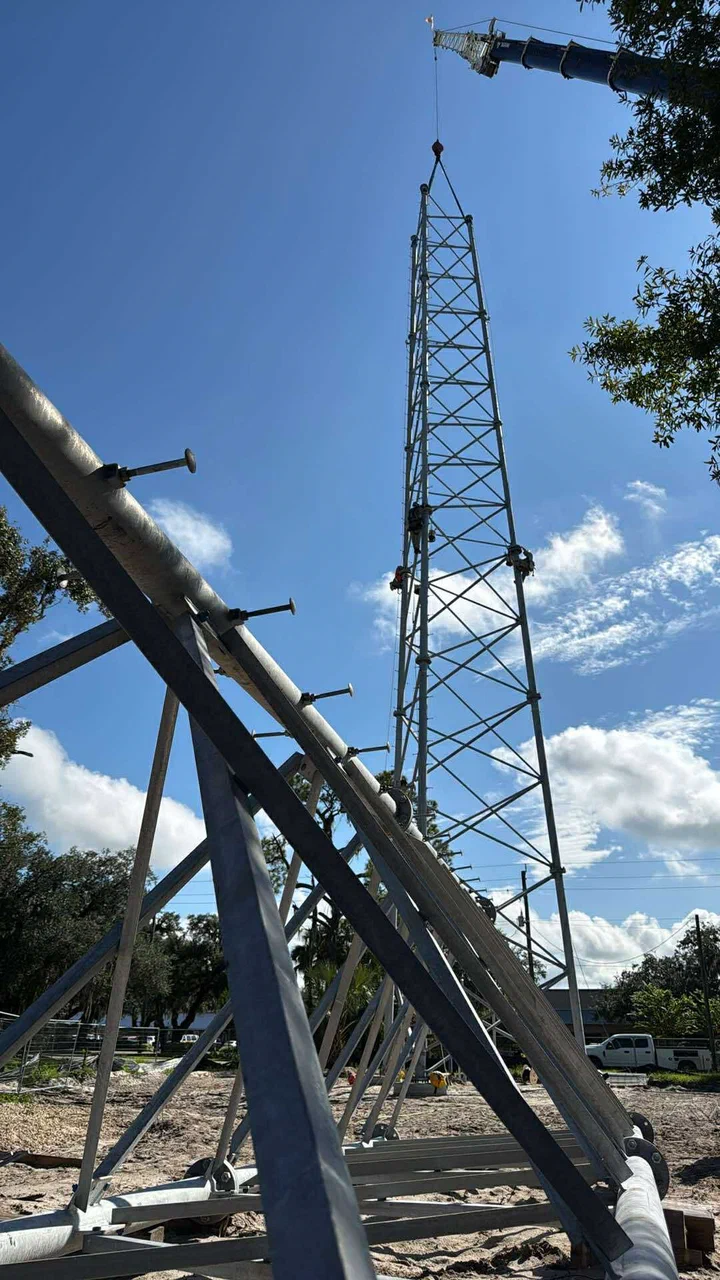
New Site Builds
Empty dirt to operational tower, one crew, one point of contact.
Grounding & Cadwelding
Ground rings, exothermic welds, bonding to NEC and manufacturer spec.
Page last updated July 13, 2026.
Tell us the site.
We'll bring the steel.
Send the location, tower type, scope, and timeline. We come back with a quote, a crew, and a schedule you can build a business around.